

Falcon
Gewinkelte runde Dunkelfeldbeleuchtung FLDR-i250-LA3-SR24
FLDR-i250-LA3-SR24
Ring / round, Angled / low-angle, Ø 230 mm, Red, 626 nm
Price and availability on request
A dark-field light for industrial machine vision couples light in at a shallow angle across the surface of the part. Edges, embossing, scratches, particles and other scattering structures light up, while smooth areas stay dark. The contrast you can achieve depends on material, roughness, feature orientation, angle of incidence, working distance, camera, lens and exposure. Product filters help you narrow down form factor, illuminated area and integration data. For a dependable choice, though, compare representative good and bad parts under the imaging conditions you will actually run.
366 products
Falcon
FLDR-i250-LA3-SR24
Ring / round, Angled / low-angle, Ø 230 mm, Red, 626 nm
Price and availability on request
Falcon
FLDR-i250-LA3-IR
Ring / round, Angled / low-angle, Ø 230 mm, Infrared, 875 nm
Price and availability on request

Falcon
FLDR-i250-LA3-UV
Ring / round, Angled / low-angle, Ø 230 mm, UV, 375 nm
Price and availability on request

Falcon
FLDR-i250-LA3-4-W
Ring / round, Angled / low-angle, Ø 230 mm, White
Price and availability on request
Falcon
FLDR-i250-LA3-4-G
Ring / round, Angled / low-angle, Ø 230 mm, Green, 525 nm
Price and availability on request
Falcon
FLDR-i250-LA3-4-B
Ring / round, Angled / low-angle, Ø 230 mm, Blue, 470 nm
Price and availability on request
Falcon
FLDR-i250-LA3-4-SR24
Ring / round, Angled / low-angle, Ø 230 mm, Red, 626 nm
Price and availability on request
Falcon
FLDR-i250-LA3-4-IR
Ring / round, Angled / low-angle, Ø 230 mm, Infrared, 875 nm
Price and availability on request
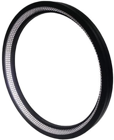
Falcon
FLDR-i280-LA3-SR24
Ring / round, Angled / low-angle, Ø 260 mm, Red, 626 nm
Price and availability on request

Falcon
FLDR-i280-LA3-RGB
Ring / round, Angled / low-angle, Ø 240 mm, RGB
Price and availability on request
Falcon
FLDR-i280-LA3-4-W
Ring / round, Angled / low-angle, Ø 260 mm, White
Price and availability on request
Falcon
FLDR-i280-LA3-4-G
Ring / round, Angled / low-angle, Ø 260 mm, Green, 525 nm
Price and availability on request
Falcon
FLDR-i280-LA3-4-B
Ring / round, Angled / low-angle, Ø 260 mm, Blue, 470 nm
Price and availability on request

Falcon
FLDR-i300-LA3-W
Ring / round, Angled / low-angle, Ø 278 mm, White
Price and availability on request
Falcon
FLDR-i300-LA3-G
Ring / round, Angled / low-angle, Ø 278 mm, Green, 525 nm
Price and availability on request
Falcon
FLDR-i300-LA3-B
Ring / round, Angled / low-angle, Ø 278 mm, Blue, 470 nm
Price and availability on request
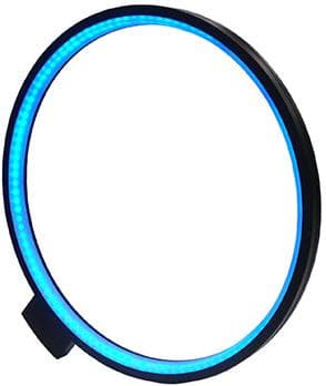
Falcon
FHDR-Si426-LA3-W
Ring / round, Angled / low-angle, Ø 404 mm, White
Price and availability on request
Falcon
FHDR-Si426-LA3-G
Ring / round, Angled / low-angle, Ø 404 mm, Green, 525 nm
Price and availability on request
Falcon
FHDR-Si426-LA3-B
Ring / round, Angled / low-angle, Ø 404 mm, Blue, 470 nm
Price and availability on request

Falcon
FLDR-Si31-LA1-W
Ring / round, Horizontal / grazing, Ø 20 mm, White
Price and availability on request
Falcon
FLDR-Si31-LA1-R24
Ring / round, Horizontal / grazing, Ø 20 mm, Red, 626 nm
Price and availability on request
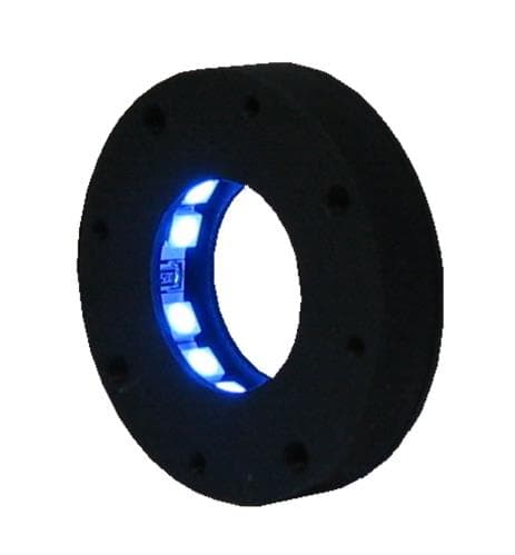
Falcon
FLDR-Si35-LA1-W
Ring / round, Horizontal / grazing, Ø 17 mm, White, Direct
Price and availability on request
Falcon
FLDR-Si35-LA1-G
Ring / round, Horizontal / grazing, Ø 17 mm, Green, 525 nm, Direct
Price and availability on request
Falcon
FLDR-Si35-LA1-R24
Ring / round, Horizontal / grazing, Ø 17 mm, Red, 626 nm, Direct
Price and availability on request
Falcon
FLDR-Si35-LA1-IR
Ring / round, Horizontal / grazing, Ø 17 mm, Infrared, 850 nm, Direct
Price and availability on request

Falcon
FLDR-i49-LA1-SR24
Ring / round, Horizontal / grazing, Ø 22 mm, Red, 626 nm
Price and availability on request

Falcon
FLDR-Si49-LA1-W
Ring / round, Horizontal / grazing, Ø 26 mm, White
Price and availability on request
Falcon
FLDR-Si49-LA1-G
Ring / round, Horizontal / grazing, Ø 26 mm, Green, 525 nm
Price and availability on request
Falcon
FLDR-Si49-LA1-B
Ring / round, Horizontal / grazing, Ø 26 mm, Blue, 470 nm
Price and availability on request
Falcon
FLDR-Si49-LA1-R24
Ring / round, Horizontal / grazing, Ø 26 mm, Red, 626 nm
Price and availability on request
Dark-field lights are incident-light lights with a very shallow angle of incidence: they sit on the camera side so that only edges, engravings and defects scatter light into the camera. Dark field is a lighting principle, not a ready-made defect detector. At a shallow angle of incidence, a smooth surface reflects most of the light away from the camera, while edges, elevations, recesses or particles scatter part of it back. Whether your particular feature becomes visible enough is not something the lighting class alone can tell you.
A rough base material scatters light of its own and brightens the background. The direction of a scratch governs how strongly it responds to directed lighting. Transparent, curved, multi-layer or soiled parts open up further reflection paths. Base the selection on the size, depth or height, orientation and permissible variation of the feature.
Ring-shaped dark-field lighting brings shallow light onto the part from every side, which suits structures with varying orientation. A directed low-angle geometry favors one direction and separates features aligned with it more sharply. Field of view, part geometry and the space you have available all feed into the decision.
Many listed versions are specified for short working distances, though the ranges do differ, so a blanket distance figure would be misleading. Check the model-specific working distance together with the illuminated area, housing dimensions, camera field of view and any shading.
These points matter most when comparing products:
Power supply, connectors and IP rating differ from version to version, so never carry missing information over from a similar model. For IR and UV, confirm the spectral suitability of the setup and the product-specific safety notes as well.
For pure print or color features, steeper front lighting usually works better. On flat reflective surfaces, coaxial lighting is a genuine alternative. Where you are mainly inspecting the outer contour and can reach the part from behind, look at a transmitted-light geometry instead. Dark field is not the answer simply because a surface is glossy; what counts is whether the shallow angle separates your specific feature.
A meaningful test covers several good parts and parts showing the smallest relevant deviation, including variation in position, surface and process. Keep camera, lens, exposure and setup as constant as possible while comparing versions. The result applies to the conditions you tested, not as blanket approval for other materials or distances.
Before testing, define which image characteristic leads to acceptance or rejection. Beyond the visual impression, look at the contrast in the relevant image area, how stable it stays across permissible variation in position and surface, and how well it separates from acceptable contamination. Lighting makes a feature visible; it does not set the evaluation or acceptance threshold on its own. You establish that threshold together with camera resolution, lens, exposure and the evaluation method.
Next technical step
Send us good and bad parts, or meaningful images, together with the field of view, working distance and imaging data. We narrow down the candidates for testing and state the conditions under which the result holds.
Describe your inspection task