
HIKROBOT
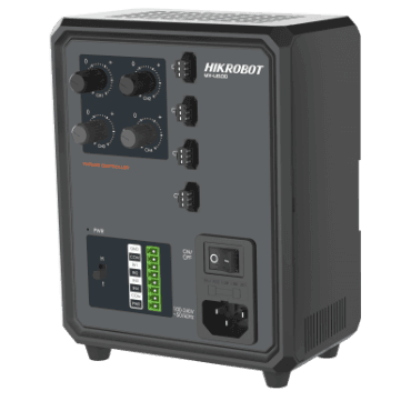
Analogue Light controller MV-LE100-120W24-4
MV-LE100-120W24-4
analog, 4 channels, 120 W total, not stated (output 24 V)
Price and availability on request
This category holds the accessories that sit on an existing light and the devices that drive it: light controllers, filters that change the light, protective covers in front of the LED surface, LED modules and replacement light sources, mounting brackets, connection and extension cables. Each of these parts belongs to a particular light series, and the manufacturer states that assignment explicitly. The filter „Suitable for“ therefore gets you to the right article faster than searching by dimensions. With a controller it is the output type that decides whether a combination is permissible at all: constant current and constant voltage are not interchangeable, and the figure is stated in the datasheet of the exact light. If you are unsure, send us the full model designation of your light. We check the assignment against the manufacturer documents and tell you what light loss and what power demand to expect.
111 products
No obligation · we usually reply within 24 hours on business days
A light controller supplies one or more machine vision lights and governs their brightness, operating mode and timing relative to the camera. It makes the lighting reproducible: the same brightness across the shift, a defined flash at the moment of exposure, and a power level the light may briefly exceed in strobe operation.
HIKROBOT
MV-LE100-120W24-4
analog, 4 channels, 120 W total, not stated (output 24 V)
Price and availability on request

HIKROBOT
MV-LE100-200W24-2BD
analog, 2 channels, 200 W total, not stated (output 24 V)
Price and availability on request
HIKROBOT
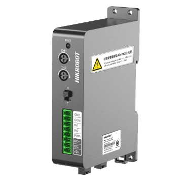
MV-LE100-24W24-2
analog, 2 channels, 24 W total, not stated (output 24 V)
Price and availability on request
HIKROBOT
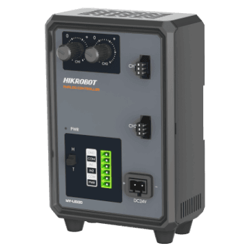
MV-LE100-48W24-2
analog, 2 channels, 48 W total, not stated (output 24 V)
Price and availability on request
HIKROBOT
MV-LE100-500W24-1ED
analog, 1 channel, 432 W total, not stated (output 24 V)
Price and availability on request
HIKROBOT
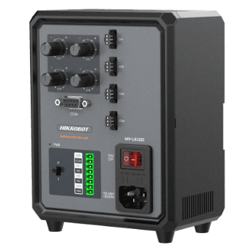
MV-LE100-60W24-4D
analog, 4 channels, 60 W total, not stated (output 24 V)
Price and availability on request
An LED module or replacement light source is the exchangeable light source of a telecentric or high-power light. It brings an existing light back into service after a failure, or changes its colour without touching the optics and the set-up.

OPT
OPT-IDD1-HLW
White, 24VDC±20%
Price and availability on request
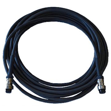
A lighting cable connects the light to the controller or extends an existing line. It brings power and control signal to the light, including where the connection moves or runs in a drag chain.
HIKROBOT
MV-LW-H-001-1-19M8A
1 m, 19M-8A → 19M-8A
Price and availability on request

HIKROBOT
MV-LW-H-001-1-S
1 m, SMR-03V-B → SMR-03V-BC
Price and availability on request
HIKROBOT
MV-LW-H-003-1-19M8A
3 m, 19M-8A → 19M-8A
Price and availability on request

HIKROBOT
MV-LW-H-003-1-S
3 m, SMR-03V-B → SMR-03V-BC
Price and availability on request
HIKROBOT
MV-LW-H-005-1-19M8A
5 m, 19M-8A → 19M-8A
Price and availability on request

HIKROBOT
MV-LW-H-005-1-S
5 m, SMR-03V-B → SMR-03V-BC
Price and availability on request
Each filter in front of a light does exactly one thing. A diffuser scatters the light and takes hotspots off glossy parts. A collimating filter narrows the beam and makes edges look sharper. A polarising film, together with a polarising filter on the lens, suppresses reflections without changing the geometry in the image. A protective cover does not change the light at all, it keeps dirt and contact away from the LED surface. So start with the question of which problem in the image has to be solved. The accessory type follows from that.
Filters and covers are cut to the emitting surface of a particular series. The manufacturer names the matching series for every article and often the individual models as well. You find these figures in the filter „Suitable for“ and in the technical data. The same edge length is not proof of a fit, because fixing, frame and thickness have to match too. Take the assignment from the manufacturer data, not from comparing dimensions.
With polarising films the orientation matters as well. They are supplied horizontal or vertical, and which one you need follows from the orientation of the polarising filter on the lens. The two only suppress the reflection once their planes of polarisation are 90 degrees apart.
Every element in the beam path costs light. A diffuser takes part of the intensity, a polarising film considerably more. Together with the filter on the lens this typically adds up to several f-stops. So check before ordering whether the remaining brightness is enough for your exposure time, especially with moving parts and short cycle times. If it is not, a stronger light or strobe operation with a matching controller is the way to go.
In telecentric and high-power lights the light source is a module of its own. If it fails, or if a different colour is needed, only that module is replaced. Optics and the established set-up stay untouched. Watch the light colour or wavelength, the supply voltage and the forward current. A module in a different colour changes contrast and exposure even when it fits mechanically.
Mounting brackets put the light at the angle and distance the application needs. With cables both connections count, as do the pin assignment, the length and the operating conditions. A mechanically matching connector on its own is no proof of compatibility. Record the combination of light, accessory and cable you actually use, with full model designations: for a later replacement that is the most reliable basis.
A light controller delivers its power either as an impressed current or as a regulated voltage. The two are not interchangeable. A light designed for constant current has no series resistor of its own and does not limit the current itself. On a constant voltage source it can therefore be driven outside its limits. Conversely, a light with its own current limiting stays darker than intended on a constant current source.
Which output type your light needs is stated in the datasheet of that exact model and cannot be derived from the product family. In our range 36 devices work with constant current and 9 with constant voltage; for the remainder the manufacturer does not name the regulated quantity, and we do not enter anything we cannot substantiate. You reach those devices through the filter option „ohne Herstellerangabe“. Send us the full model designation of your light and we will settle the assignment before you order.
In continuous operation the light is on all the time. That is the simplest mode and usually enough for slow or stationary parts. In strobe operation the controller switches the light on only for the duration of the exposure. Moving parts are imaged more sharply, ambient light matters less against the flash, and the LED stays cooler.
Strobe operation also allows the light to be driven briefly beyond its continuous current. That reserve is tied to pulse width and pulse pause, and both limits are stated in the datasheet of the light, not of the controller. Exceeding them shortens the life of the LED or destroys it. So before using overdrive, check what pulse current the light permits and what pulse width the controller actually delivers.
The number of channels tells you how many lights can be controlled independently. In our range it goes from one to sixteen. Several channels pay off when an inspection station works with different lighting directions in sequence, or when bright field and dark field have to stay separately controllable.
The channel count alone is not enough, though. What matters is whether the sum of all connected lights stays within the total power of the device. The devices in our range cover 4 to 1450 watts, and some controllers deliver less per channel than their total power suggests. So work with power per channel and total power separately; both are in the short profile of every device.
In strobe operation the light has to be there at the moment the camera exposes. The trigger comes either from the camera itself, from a higher-level controller or from the internal trigger of the light controller. The devices in our range accept switch and level triggers, some also distinguish between rising and falling edge.
Depending on the device the response time is between a few and a few hundred microseconds. For short exposure times and fast cycles that is a selection criterion and not a minor figure: exposing for 50 microseconds does not go together with a 200 microsecond delay in the signal path. Budget for the delay of camera and controller as well, and measure the chain once at the end.
Analogue controllers are set on the device, with a knob or with keys. That is enough for a fixed set-up that is established once and not changed afterwards. Digital controllers can additionally be adjusted from the line, in our range over RS232, RS485 or Ethernet. Brightness is adjustable in 256 steps there, so a recipe change is possible without touching the device.
For later operation that is more than convenience. A documented brightness step can be reproduced after maintenance, a knob position cannot. So record the step, the pulse width and the delay the line was signed off with.
Next technical step
Send us the full model designation of your light and the goal in the image: fewer reflections, more even illumination, more directional light or a clean flash at the moment of exposure. We name the matching accessory and the matching controller from the manufacturer documents and tell you what light loss and what power demand to expect.
Have accessories and controllers checked